CForth Hardware for STM32G431 and STM32F042 DIY Construction Manual
Primarily CForth was developed for a 32pin LQFP STM32G431KB processor, a compatible hardware design is described here. In CForth context, STM32G441 processors are 100% compatible with STM32G431. For this reason only STM32G431 is used for both below.
From this basic version, a small CForth based USB/DMX controller board with STM32G431KB was derived and finally a simplified "Black Pill" pinout compatible version for STM32G4xx LQFP48 case (called "Grey Pill").
Additionally firmware for 20pin TSSOP STM32F042F6 and 32pin LQFP STM32F042K6 was developed and a compatible hardware proposal is described. Works with STM32F070, too.
Because it is complicated to etch PCBs without appropriate tools, Veroboard compatible PCB layouts are presented here. Because such a layout is quite coarse, also etching is possible with simple equipment.
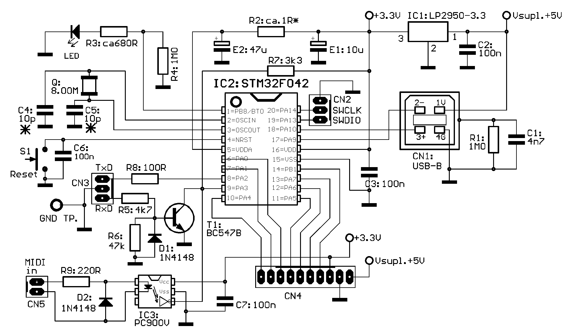
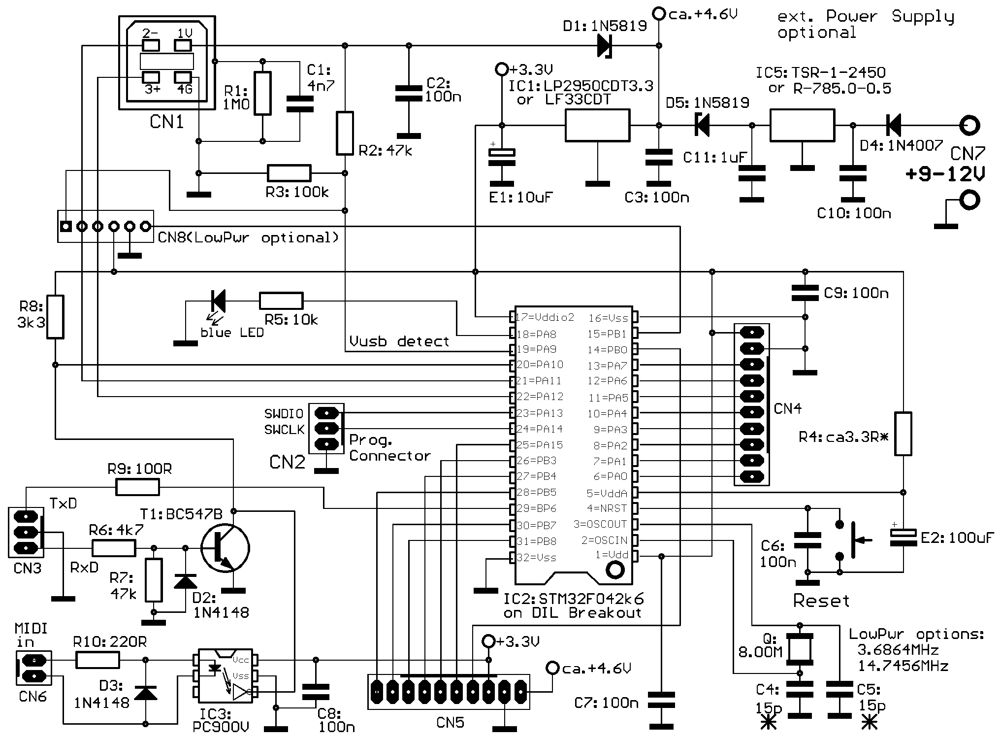
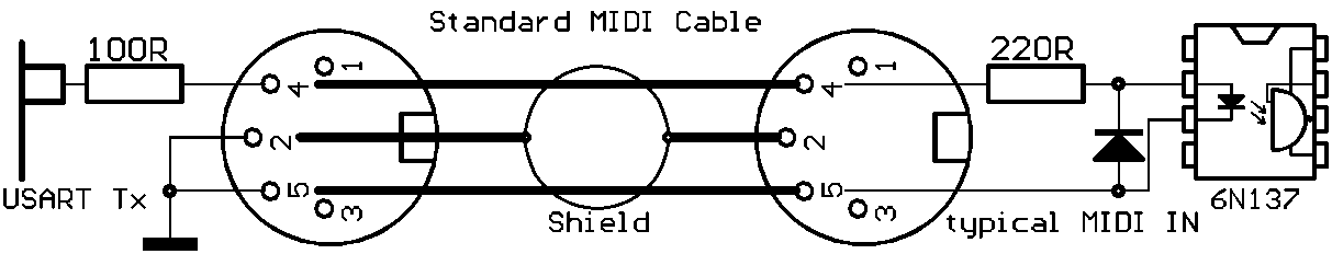
The actual hardware USART Tx output is designed without external inverter/driver, the idle low level is obtained by inversion at USART register level. For this reason, the TxD "logical 0" level is only 3.3Volt, a 100 Ohm resistor is added as short circuit protection. This has been tested with several third party RS-232 inputs, which typically have a trigger level around 0.7 Volt and an input impedance in the order of 5kOhm.
Somewhat more critical is the use of this Tx driver as MIDI OUT. With a modified connector wiring (see below) commonly used MIDI interfaces are safely driven with 5mA or more.
Hardware for STM32G431KB
Old versions (<7.55) have partially different I/O connections
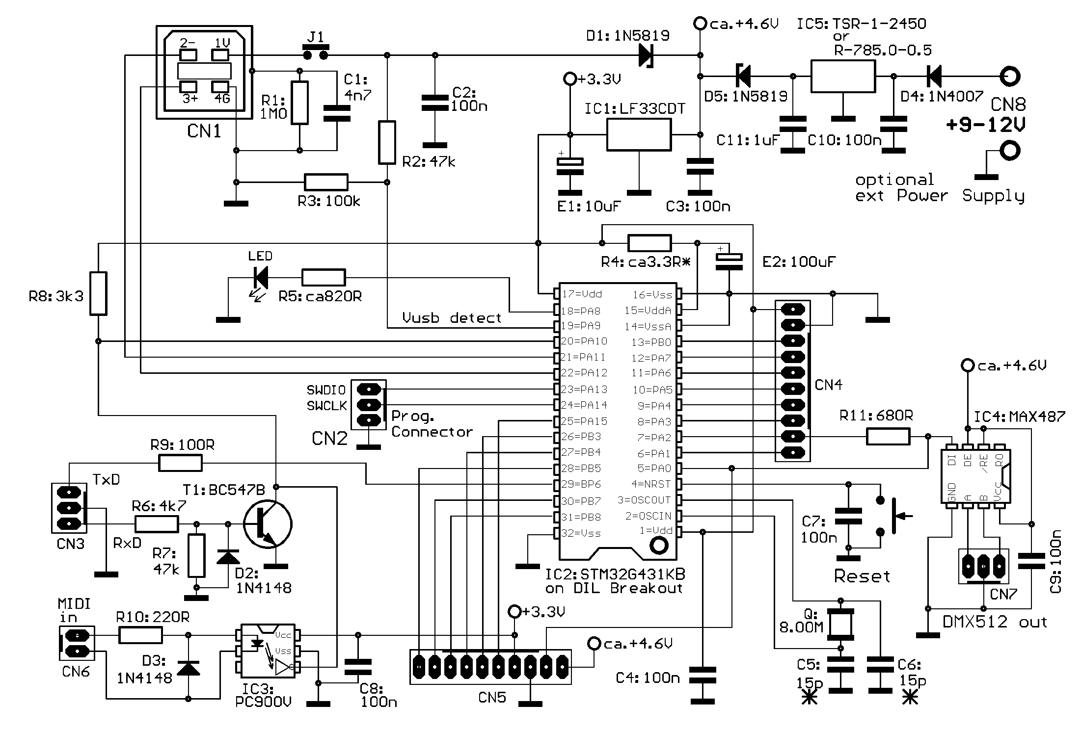
For most users MIDI IN and DMX OUT probably will not be interesting. External power can easily be supplied via USB connector. But CForth programming and optimizing of external hardware expansion is annoying without RS-232 interface, because the USB virtual Com terminal connection breaks down after every CForth hardware reset. The USB terminal must be closed before and started new when the USB connetion is re-established.
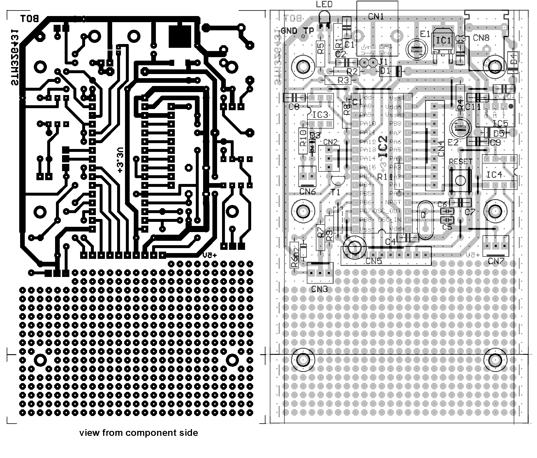
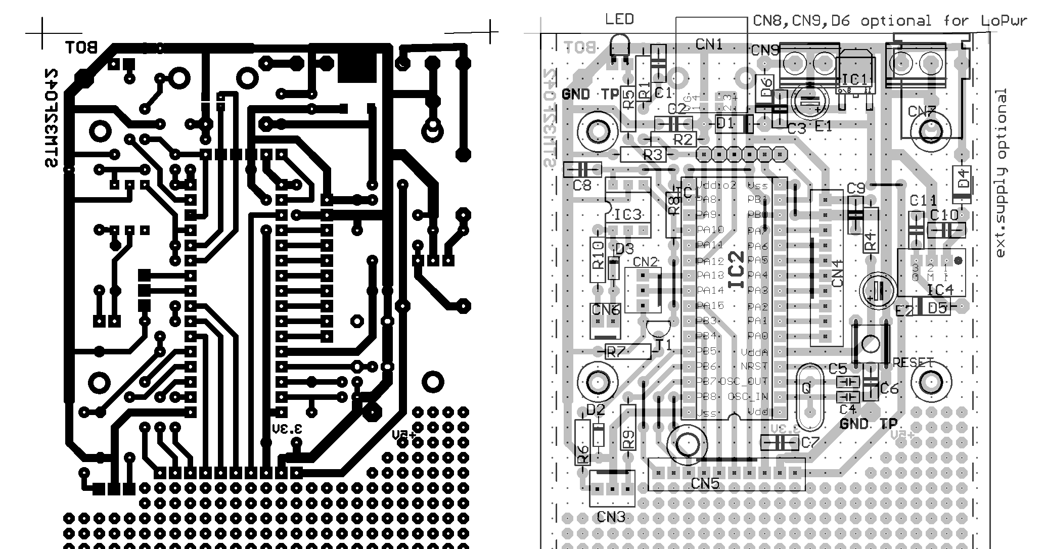
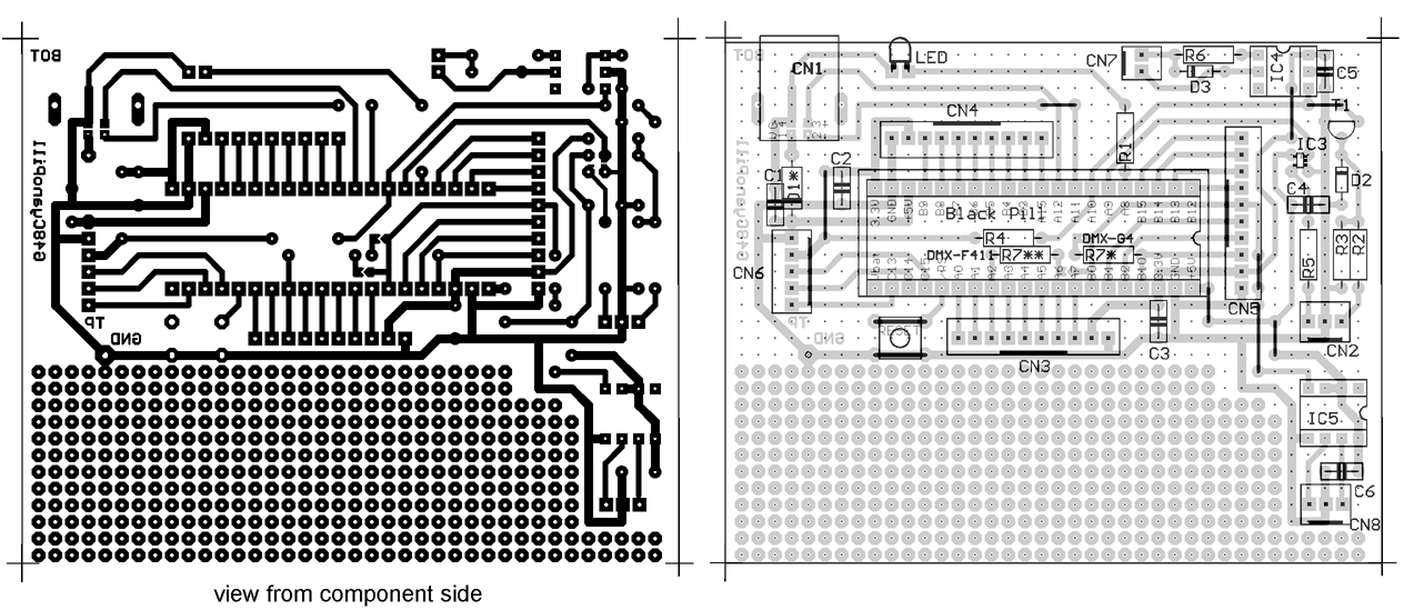
BOTTOM layer as well as component placement view are "from component side", i.e. BOTTOM layer shown mirrored "through the PCB" (as needed for PCB production))
Veroboard layout after some redesign.
Parts marked with * (star):may need individual optimization: R4 depends on VddA current drain. For best filtering, it should be as high as possible, but then low freq ripple might increase and (Vdd – VddA) must be less than 0.3V. Recommended drill diameters for etched PCB:
resistors, capacitors, diodes, transistor, ICs, jumper wires 0.8mm; LED, connectors 1.0mm;
USB socket: 0.8mm/metal flag 2.0mm or jigsaw slît, CN8 jigsaw slits, fixture holes 3.0mm
Special parts: (cited suppliers are examples where private consumers can buy in Germany)
---STM32G431KB or STM32G441KB: Reichelt, tme.eu, Mouser et.al.
---LQFP to DIL32 breakout board: e.g. Adafruit 1163 (Conrad). It is strongly recommended to scratch off solder resist and mount three small capacitors 100nF between Vdd/Vss and VddA and VssA as near as possible to the microcontroller on the breakout board. ---CN8 (ext.power supply): ROKA brand, Conrad 737992. The minus pins are soldered together at connector bottom side, so only one through hole is used. Other types of power connector may be used, of course. ---LED: standard 2mA type. For a blue or white LED, R5 should be increased to about 4k7 Ohms.
---Optocoupler: PC900V; source Conrad 184098
---connectors MIDI/RS-232/programmer: PS 25/2G BR, PS 25/3G BR or Conrad 743089 / 741221
---peripheral connectors: source Reichelt PS 25/10G BR Conrad 741264
Small USB/DMX controller with STM32G431KB
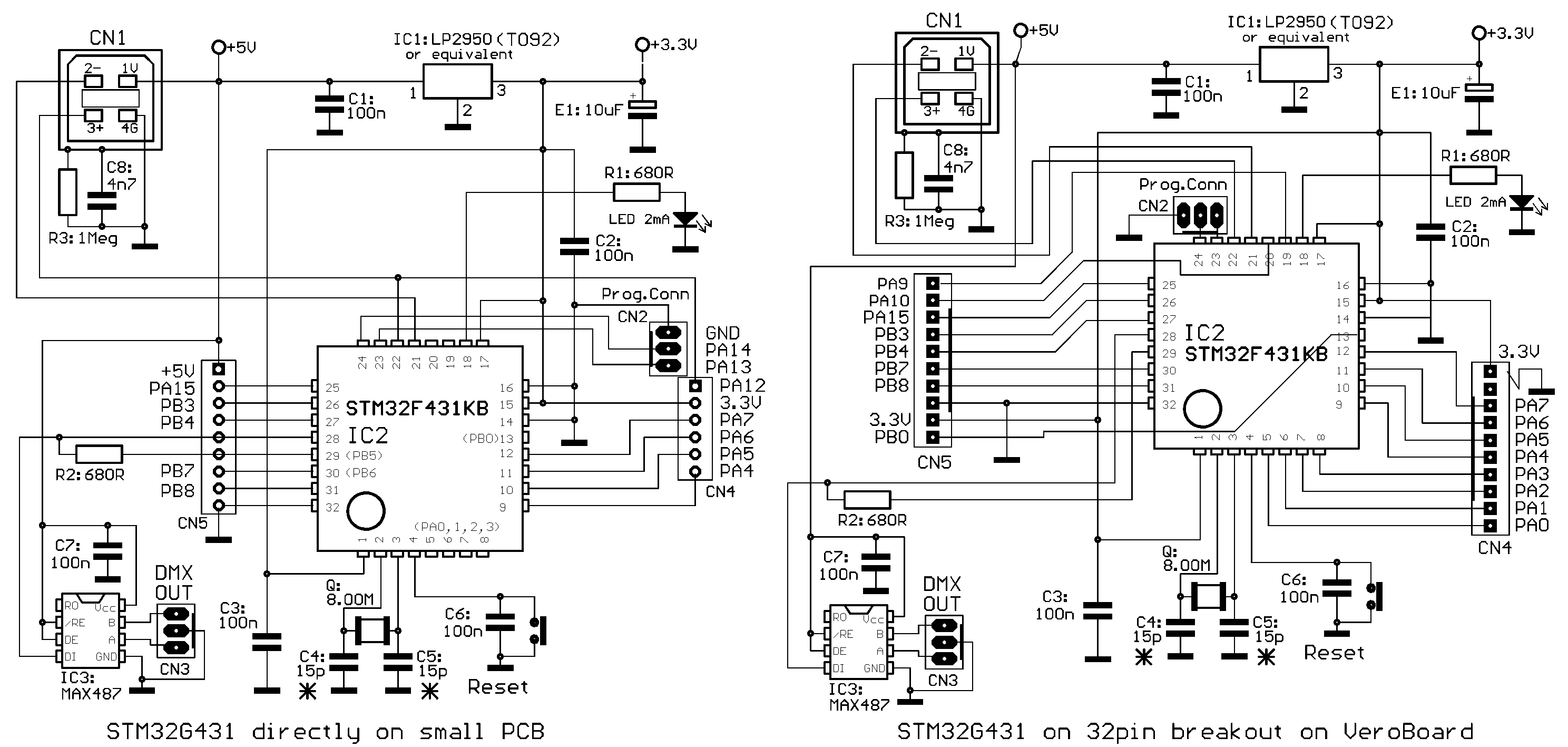
Download the Veroboard layout as 1:1 TIF file for PCB production
BOTTOM layer as well as component placement view are "from component side", i.e. BOTTOM layer shown mirrored "through the PCB" (as needed for PCB production))
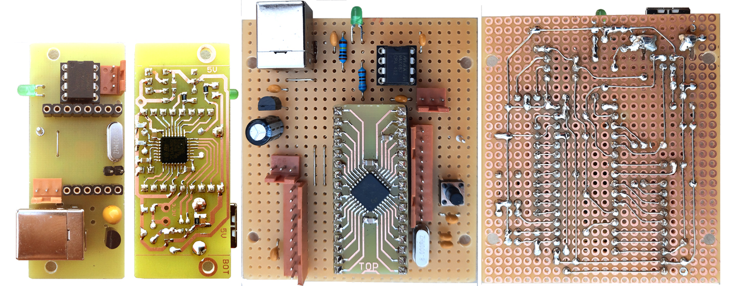
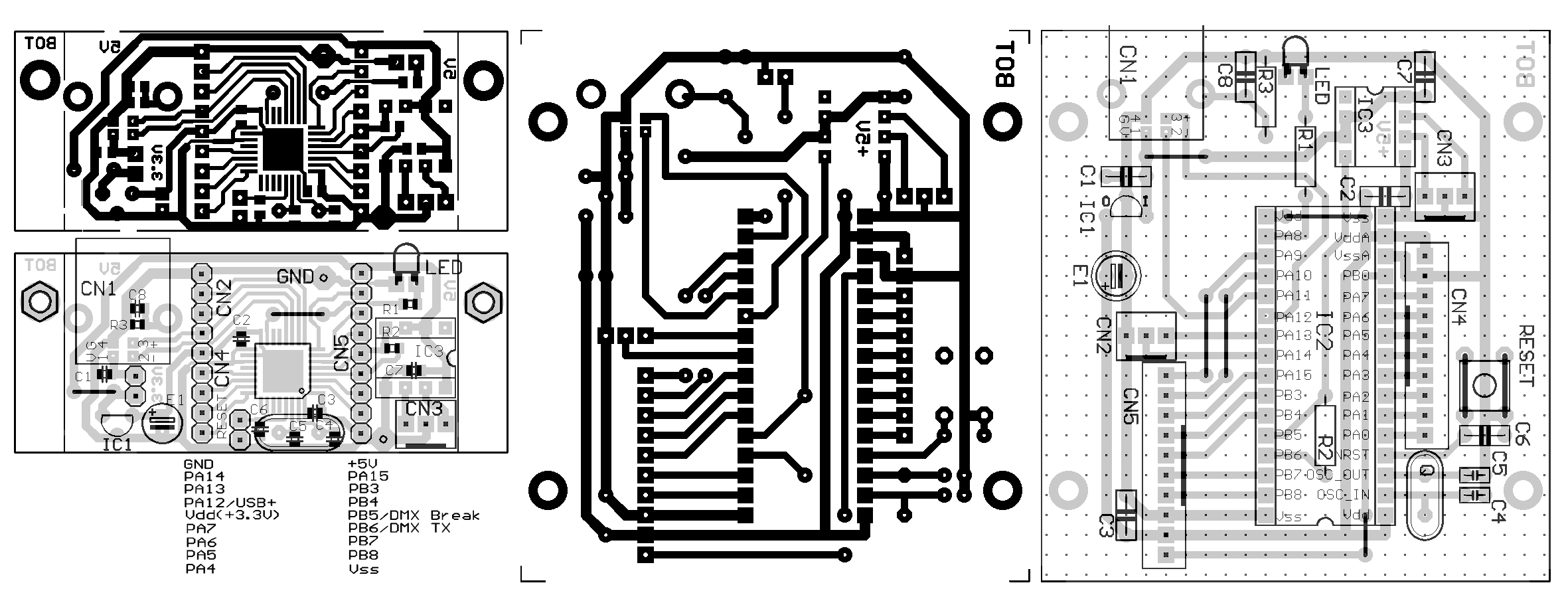
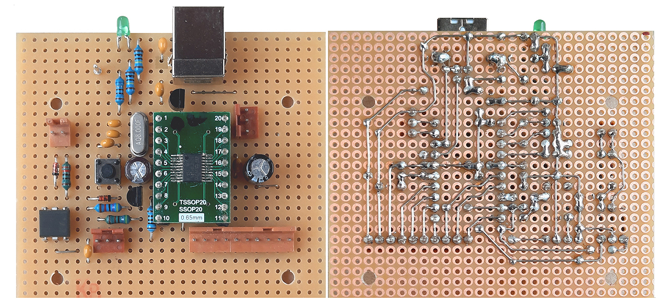
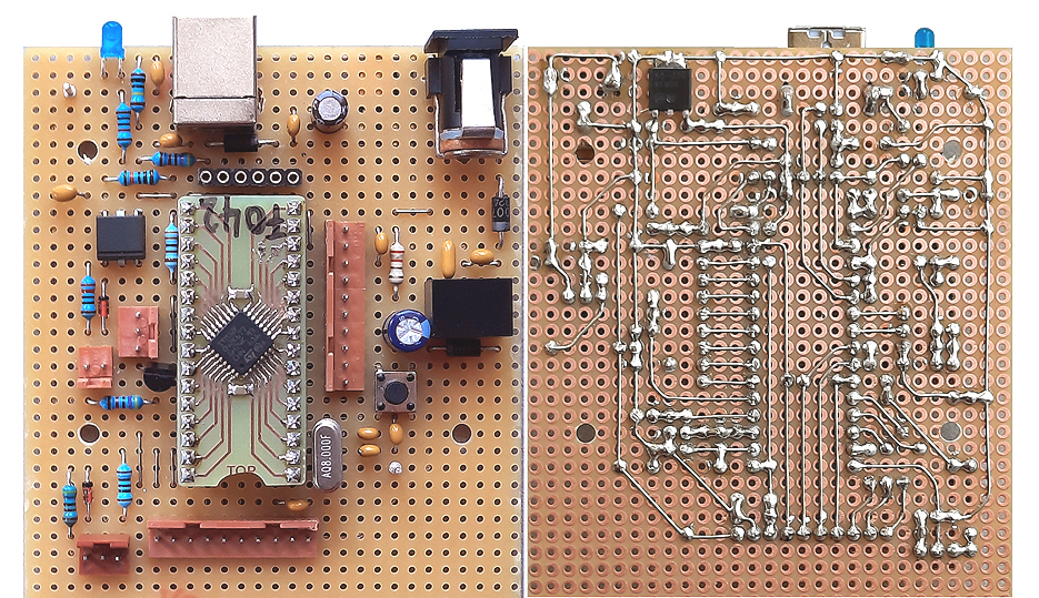
Hardware for STM32F042F6 (20pin TSSOP) (works with STM32F070F6, too)
BOTTOM layer as well as component placement view are "from component side", i.e. BOTTOM layer shown mirrored "through the PCB" (as needed for PCB production))
Special parts: (cited suppliers are examples where private consumers can buy in Germany)
---STM32F042F6: tme.eu, Mouser et.al.
---TSSOP to DIL20 breakout board: e.g. Adafruit 1205 (Conrad) and others.
---LED: standard 2mA type. For a blue orwhite LED, R3 should be increased to about 4k7 Ohms.
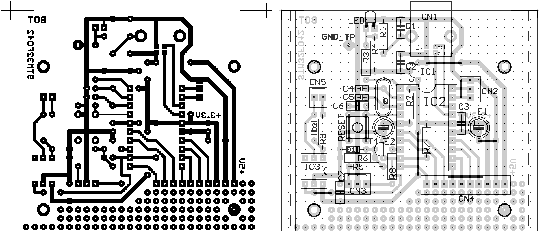
Hardware for STM32F042K6 (32pin LQFP) (works with STM32F070K6, too)
Hardware for STM32G4xx (48pin LQFP) "Black Pill" compatible pinout ("Grey Pill")
This PCB is intended for easy support of a "Black Pill" standalone module with some practically useful peripherals. Specifically it may be assembled (or not) with a combined RS-232/MIDI interface and a DMX512 lighting control transmitter plus some area for user specific completion.
My "Grey Pill" design is a simplified Black Pill pin compatible PCB for LQFP48 STM32G4xx processors. It does not have the USB connector, Reset button and BOOT0 button onboard. So this PCB is needed for practical use of the "Grey Pill" module.

"Grey Pill" and original Black Pill have assigned the DMX transmitter at different processor ports. For this reason, the appropriate resistor R7* or R7** must be connected via solder bridge.
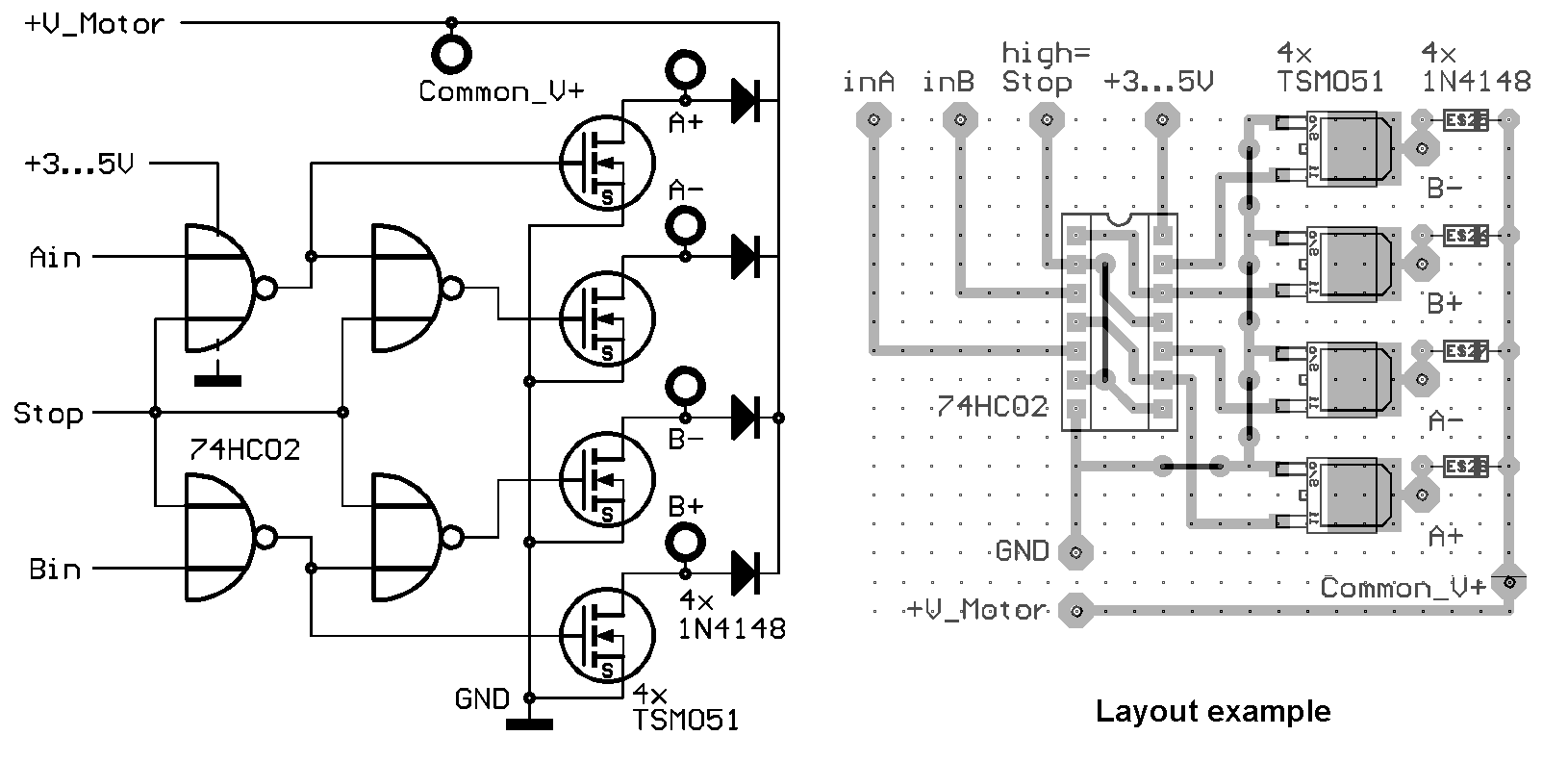
Additional hardware for Stepper and DC Motor control
The actual firmware supports control of stepper motors (kernel ops MOT1, MOT2, MOT3).
To save I/O pins, a simple converter circuit is proposed to convert a two line phase step sequence into a four line sequence to be used for unipolar stepper motors:
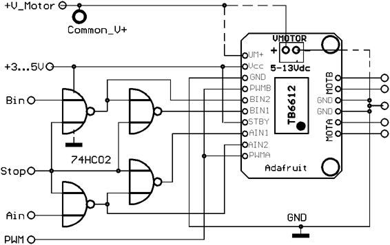 For connection with TB6612 dual H bridge driver (Adafruit breakout board recommended), the four 74HC02 outputs are connected with corresponding TB6612 pins.
PWM A,B pins are connected with corresponding PWM I/O pin. This way, the speed of commutated DC motors can be regulated. For stepper motors, the PWM must be set at maximum level. High Stop level sets all motor outputs to high impedance, 0 PWM sets all outputs to LOW. |
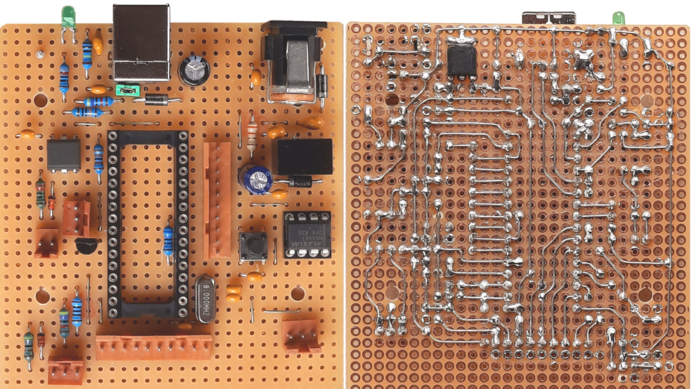
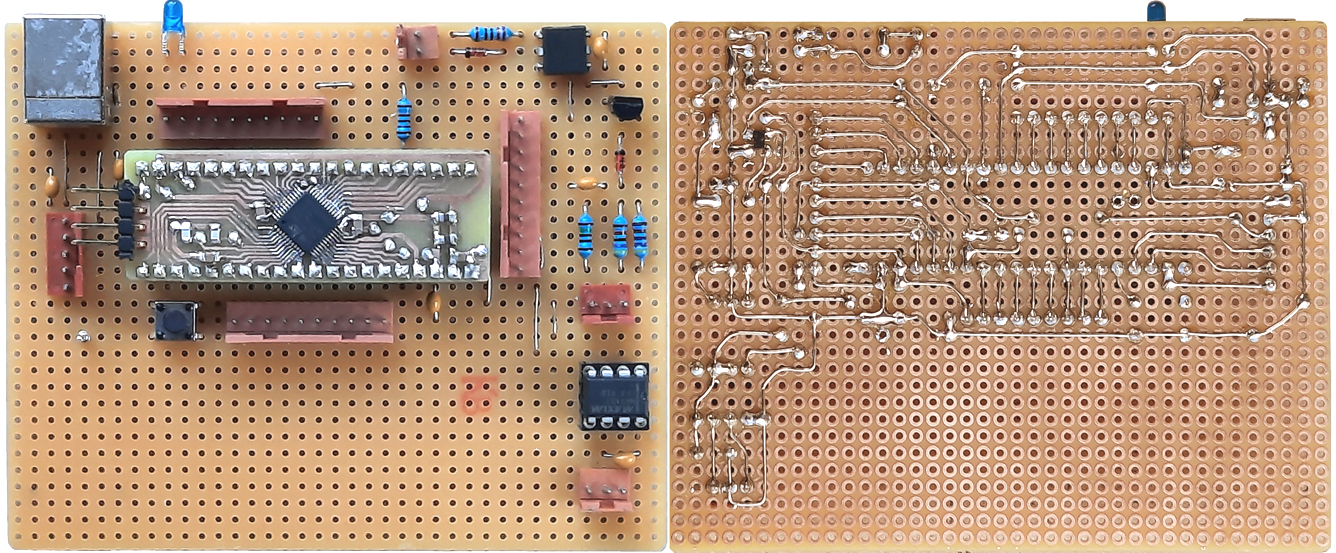
Hints for Veroboard assembly
MIDI OUT with 3.3 V "logic0" level:
contact: wschemmert@t-online.de, www.midi-and-more.de
It is useful to print a mirrored version of the placement drawing to get a view from bottom=solder side.
The diameter of the wire should be 0.5 or 0.4 mm for easy bending and diagonal wiring between the neighboured copper dots. A set of "adjustment" pliers with small flat tips (or stable tweezers) is recommended for bending and positioning the wires. For 45 degree bendings, a small screw driver pressed on the wire is helpful.
The correct positioning of parts is essential, because there is almost no reserve for alternative positioning. The final solder process is less complicated than it looks. So it is recommended first to place all parts (bigger and typical parts first) and solder them as slightly as possible only to fix them provisionally. Next cut longer wires of fixed components about 1 mm above the Veroboard for later final soldering. At this stage, parts with more than two contacts like connectors should be soldered only at 2 diagonal edge pins. Try to organize the solder sequence in a way that one alreay soldered point is connected with another yet unsoldered, if possible. Points wit 2.5 mm distance are not soldered with a wire, but with a dot of solder instead. If you are connecting points with 3.6 or 5mm distance, becareful not to unsolder the already soldered point due to much heat on the wire.
In some cases jumper wires must be placed before IC sockets. Length and position of all wires (except USB data lines) is uncritical. So if something goes wrong, forgotten or non-placeable wires can be put later directly with isolated wire.
PC900V + 220Ohm: 6.2mA, 1N137(different manufacturers) + 220Ohm: 4.8..5.6mA,
iRig Midi2: 6.4mA very old MIDI Sport4x4: 6.2mA, newer MIDI Sport1x1: 5.6mA
The drive current depends strongly on the forward voltage drop of the optocoupler LED.
Typically the optocouplers used for MIDI interfaces need a trigger current of ca. 2mA.
Care must be taken about pin PB8, which supports the alternative BOOT0 function.
At both boards this is inhibited by the LED (additionally by R4 at STM32F042)
For the STM32G431 board it is recommended to deactivate this function: connect ST-LINK, open "Target" menue / "Option Bytes" click Checkbox "BOOT LOCK" and quit with "Apply".
In case of trouble, connect PB8 provisionally to Ground with an 100kOhm resistor or similar.
* Right of technical modifications reserved. Provided 'as is' - without any warranty. Any responsibility is excluded.
* This description is for information only. No product specifications are assured in juridical sense.
* Trademarks and product names cited in this text are property of their respective owners.