Simple USB to DMX512 Interface for Arduino Micro or Leonardo
This is a do-it-yourself construction manual for a simple USB interface to control a DMX512 lighting bus.
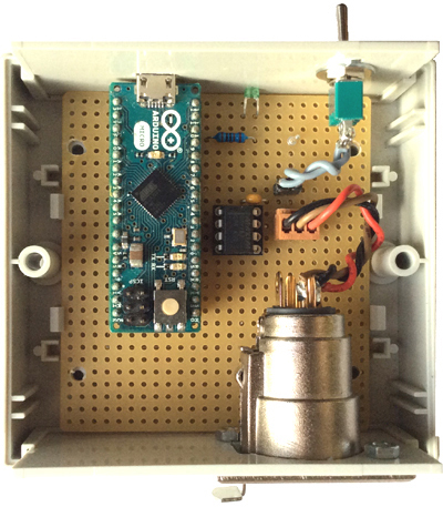
The basic part is an Arduino Micro module, completed with a minimum number of additional components. The PCB layout is optimized for straightforward reproduction on a Veroboard.
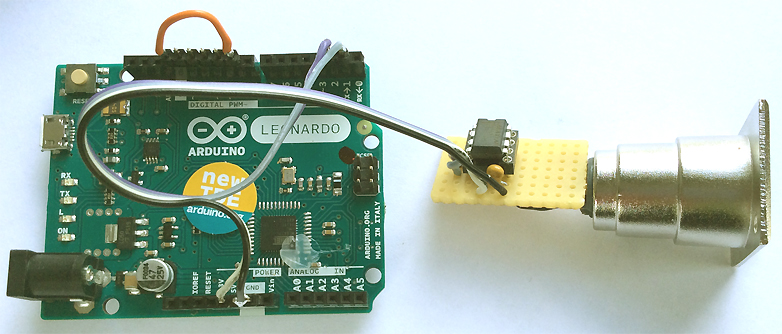
An Arduino Leonardo can be completed with a DMX transmitter even more simply (see below).
The firmware for both models differs minimally but is supplied as separate files.
Following features are the same for both hardware:
Due to the limited SRAM size of the ATmega32U4 microcontroller (the soft fade feature needs a lot), the number of accessible DMX channels is max.256. Because this firmware makes use of the ATmega Boot Section (code for storage of user created lighting scenes in Flash), it can only be programmed with an external ISP programmer, not with a bootloader.
Three different command sets are selectable by a jumper or switch:
An alternative firmware is available for download, which supports the MiniDMX protocol for 512 DMX channels if the jumper is placed (or switch closed).
Assembly of the Arduino Leonardo version (schematic see manual):
Downloads:
A detailled construction- and operation manual (PDF file) is available
Veroboard and PCB layout for Arduino Micro
Veroboard solder side view for Arduino Micro
DMX solder connection view for Arduino Leonardo
Changes of all firmware variants Version 1.14 , 01 November 2021: Code tightened, some command codes changed for better compatibility with STM32 DIY versions, bugfix(MiniDMX@Alternative Firmware) else minor improvements).
Standard Firmware for Arduino Micro: MIDI or ASCII text command set (256 DMX channels) selectable.
Alternative Firmware for Arduino Micro: MiniDMX (512 DMX channels) or ASCII command set (256 DMX channels) selectable.
Standard Firmware for Arduino Leonardo: MIDI or ASCII text command set (256 DMX channels) selectable.
Alternative Firmware for Arduino Leonardo: MiniDMX (512 DMX channels) or ASCII command set (256 DMX channels) selectable.
Formally this is implemented here as ASCII command 'Z' (hex 5A). This letter is the header byte of each MiniDMX data packet. So when it gets received, the microcontroller jumps into an endless corresponding decoder routine and returns back to the ASCII command mode after a timeout when no more MiniDMX packets are received or if a severe protocol error was detected. Because MiniDMX permanently transfers the levels of all DMX channels, fade processes, prestored lighting scenes and the chaser are not supported by this mode. MiniDMX is compatible with free lighting control software like DMXControl3 (used for test here) and Freestyler.
Unfortunately the original website with the MiniDMX specification is not online anymore.
Most essential features:

It is implemented instead of the MIDI command set. Without jumper/switch (default) the standard ASCII command set as described above is active. In both positions, the microcontroller is configured as USB Communication Device (CDC/ACM class) and is seen as a virtual COM port by the host.

If the orange jumper (connects IO9(PB5) with Ground) is set, USB starts as virtual MIDI interface with the MIDI command set (or 512 channels MiniDMX, depending on the installed firmware version).
When it is removed (default), USB is configured as a virtual serial port and the ASCII/MiniDMX command set supporting 256 DMX channels, is active.
The black wire is Ground, the white wire is +5V. The grey wire sends DMX from Arduino TX (D1), the violet wire (D2) disables the DMX transmitter during USB enumeration.
Connections are made with 2.54mm pinheads, nothing is soldered at the Arduino.
The subsequently downloadable material is copyrighted (c)2015-21 by Wolfgang Schemmert.
Assembly and use of the interface is permitted for free by everybody for any purpose ("freeware")
The MiniDMX firmware is provided under "Creative Commons 3.0 DE License"
All information is based on best knowledge, but without any warranty. Any responsibility is excluded.
1:1 TIF format. BOTTOM layer as well as component placement view are "from component side", i.e. BOTTOM layer shown mirrored "through the PCB" (as needed for PCB production)
(PNG, not scaled)
(JPEG, not scaled)
Recommended Fuses configuration: extended 0xF9, high 0xCF, low 0xFF
Recommended Fuses configuration: extended 0xF9, high 0xCF, low 0xFF
Recommended Fuses configuration: extended 0xF9, high 0xCF, low 0xFF
Recommended Fuses configuration: extended 0xF9, high 0xCF, low 0xFF
* State of information November 2021.
* Right of technical modifications reserved. Provided 'as is' - without any warranty. Any responsibility is excluded.
* This description is for information only, without any warranty. No product specifications are assured in juridical sense.
* Trademarks and product names cited in this text are property of their respective owners.
 back to menue