 back to CForth features
CForth based USB/DMX controller with STM32G431
This is an experimental approach for a minimal user programmable USB/DMX512 controller to create auto-running or interactive lighting sequences. Several CPU I/O pins are user programmable, some with special features like ADC in, DAC out, SPI interface.
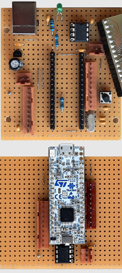
The first approach in 2020 was a "mini" version of G431 CForth. Actually a STM32 Nucleo32-G431 board was added with almost the same CForth and I/O HW features. Some hints to configure this module for best use with CForth, see bottom of this page
These devices are not intended for big stage shows. But the CForth interpreter provides good possibilities to create time based or interactive sensor animated lighting art objects or light installations for buildings or similar.
Originally this project was designed with a more conventional ASCII and MIDI based command set without possibility to create some kind of time-based action flow. The STM32 Nucleo32-G431 is much easier for user specific DIY, but does not support this original command set.
The firmware is a special version of the
CForth interpreter with
an additional set of DMX related kernel operators (Forth "words") as:
- select the DMX channel ("slot") for subsequent actions
- set DMX levels by different methods
- Hue, Saturation and Luminance of RGB lamps can be set with one command (group of 3 DMX channels)
- set the fade time for DMX level transitions
- "Panic" switch: all DXM levels to zero
- up to 97 lighting scenes can be stored permanently in the microcontroller flash and can be reloaded completely or in parts by CForth command.
- read actual DMX levels ASCII text formatted via terminal
Most essential general features of the CForth-DMX module:
- the terminal is provided via USB as virtual COM port
- with an external USB power bank, standalone operation of a programmed sequence is possible.
- for this reason, an AUTOEXE feature is implemented, which starts a complex program sequence at power on.
- some manual control of a running show is possible via terminal.
- in addition to DMX bus control, some analog or digital inputs, 2 DAC are provided and handled by CForth kernel operators
- an SPI interface, an I2C bus, two PWM pulse outputs and a motor driver are supported by firmware and externally accessible via connector array.
A hardware DIY Construction Manual for STM32G431/G441 and STM32F042
(HTML file, jumps to "minimal USB/DMX conroller" description) is provided here.
Downloads:
The subsequently downloadable material is copyrighted (c)2020-25 by Wolfgang Schemmert.
Assembly of the devices, programming and use of the software is permitted for free by everybody for any purpose ("freeware"). For commercial use, restrictions of third-party software contributors (Segger GmbH, STM) must be respected.
All information is based on best knowledge, but "as is" and without any warranty. Any responsibility is excluded. Use for dangerous, life-threatening and medical applications is forbidden.
Firmware "CForth-G4xx-MINIDMX48.hex" for "minimal USB/DMX conroller", SysClock = 48MHz
(31 March 2025 - bugfix number of pre-reserved VARCOMs)
Firmware "CForth-G4xx-MINIDMX144.hex" for "minimal USB/DMX conroller", SysClock = 144MHz
(31 March 2025 - bugfix number of pre-reserved VARCOMs)
Source code "CForth-G4xx-v65.zip"
(state 01 April 2025) This source code is provided as complete "Segger Embedded Studio" project (ZIP file,948 kB).
Parts published by Segger GmbH are under license of Segger&|Rowley, parts published by STM are under license of STM, parts programmed by me are provided under GNU GPL3 license.)
Firmware "CForth-G431Nucleo32-HSI48.hex" for "minimal USB/DMX conroller", internal RC oscillator, SysClock = 48MHz
(01 April 2025 - first release)
Firmware "CForth-G431Nucleo32-HSE48.hex" optimized for "STM32G431 Nucleo32 support board", onboard 24MHz crystal clock, SysClock = 48MHz
(01 April - first release)
Firmware "CForth-G431Nucleo32-HSE144.hex" optimized for "STM32G431 Nucleo32 support board", onboard 24MHz crystal clock, SysClock = 144MHz
(01 April 2025 - first release)
Source code "CForth-G431Nucleo-v22.zip"
(state 01 April 2025) This source code is provided as complete "Segger Embedded Studio" project (ZIP file, 502 kB).
Parts published by Segger GmbH are under license of Segger&|Rowley, parts published by STM are under license of STM, parts programmed by me are provided under GNU GPL3 license.)