Simple Li-ion Charger
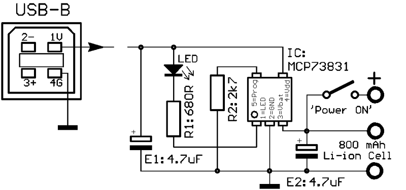
To make reconstruction as easy as possible, a single layer PCB with 2.54mm Veroboard compatible layout and standard through hole components is described here. Size of electronics 30x20mm, with 14500(=Mignon size) accumulator and fixing strip 100x28mm.

Electronics details:
IC pin1 --> socket pin1
IC pin3 --> socket pin3
IC pin4 --> socket pin4
IC pin5 --> socket pin6
To improve longtime stability, the wires are fixed with solder on the socket.
(A more compact design is possible when E1, E2 (both as X7R or X5R multilayer capacitors), R2 are soldered as 0805 SMD parts directly on the socket.)
The value of R1 is given for a standard 3mA red LED. For solar driven chargers, it is recommended to use a blue or white high efficient LED with R1=10kOhm.
With a moderately discharged accumulator (V=3.8V under 70mA load) the initial charge current (R2=2.7kOhm) is about 400mA. After 30 min ca.200mA, after 1h ca.50mA, soon after charge terminated.
The prototype shown above is powered via a standard USB power supply. The MC73831 IC is specified for input voltages up to 6V. Solar chargers may need an extra voltage limiter (Zener diode, e.g.) or step-down regulator.
For charging bigger accumulators, R2 may be lowered down to 2.0 kOhm (=max 500mA charge current).

Download:
The subsequently downloadable material is copyrighted (c)2022 by Wolfgang Schemmert.
Assembly and use of the device is permitted for free by everybody for any purpose ("freeware")
All information is based on best knowledge, but without any warranty. Any responsibility is excluded.
Single layer Veroboard compatible PCB layout
(1:1 TIF format).
The layout is seen "through" the PCB from component side, as usually needed for PCB production.
* Right of technical modifications reserved. Provided 'as is' - without any warranty. Any responsibility is excluded.
* This description is for information only. No product specifications are assured in juridical sense.
* Trademarks and product names cited in this text are property of their respective owners.
