
Simple Digital Sine Wave Generator
This was my first attempt in digital audio signal processing. By the way, I need a compact signal generator next to my PC for further experiments in this area.
The ATXmega is not the first choice for digital audio, but I have long time experience with and the necessary tools for this processor type.
To check audio circuits for musical instruments, the sine wave generator should be able to send min. 10 kHz upper frequency. On the other hand, to keep the critical firmware loop as simple as possible, the number of DAC steps per sine wave period should be a power of two (to get cyclic memory read adjusted easily).
As the max. output update frequency of the ATXmega internal DAC is 1 MHz, basically a number of 64 DAC steps per sine wave period was chosen, which results in a max. sine wave frequency of 15.6 Kilohertz. When the output frequency is lowered, the number of CPU clock cycles per DAC output is increased step by step, until a DAC output frequency of 500kHz is reached. Then the number of DAC steps per sine wave period is doubled to 128 and the number of CPU clock cycles per DAC output is increased to 1 MHz again. Next with decreasing frequency the number of CPU clock cycles is increased again down to 500 kHz per DAC output, the number of steps per sine wave period is doubled again ... and so on ... down to 40 Hz sine wave output.
Because the critical timer interrupt may comprise max. 32 CPU clock cycles, the code is written in assembler language, all variables are held in registers. Further details about the firmware see comments in the downloadable source code.
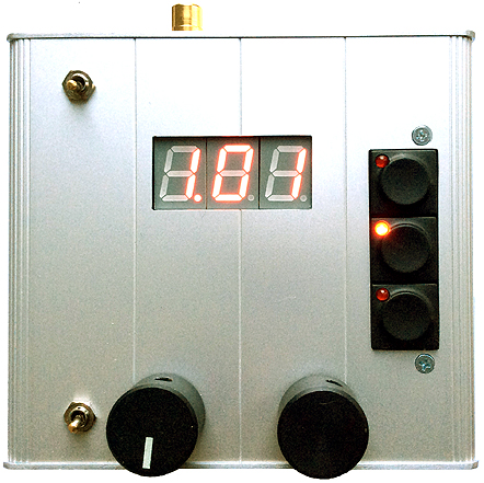
Frequency setting is done by a low cost rotary encoder (ALPS Stec 11B). Due to this concept, only discrete output frequencies are selectable.
To save as much CPU time as possible, the sine wave amplitudes for every number of steps per period were precalculated by a small console program written in C and stored in a text file which is directly formatted in Atmel assembler language format. Additionally this program calculates the frequency of every possible sine wave output in a 4 byte format, which is easily sent to the 3 digit 7 segment display, including correct position of the decimal point. This tool may be helpful to modify the device for other waveforms (e.g. triangle or sawtooth).
By a set of 3 push buttons with LED, 3 independent output frequencies may be adjusted, recalled and modified independently. Default values are 200 Hz, 1.01 kHz, 5.00 kHz.
Finally, to smoothen the DAC steps in the analog output, an analog 3rd order lowpass filter and driver amp with an overall cutoff frequency of about 70 kHz is added. This is an experimental compromise between a flat amplitude output up to 15.6 kHz and sufficient sine wave smoothing at 500kHz DAC output.
More or less as a programming experiment, the output wave form may be changed to a square wave with same frequency. Because the analog amplifier is not well suited for this waveform, this option is not made selectable at the finally produced device.
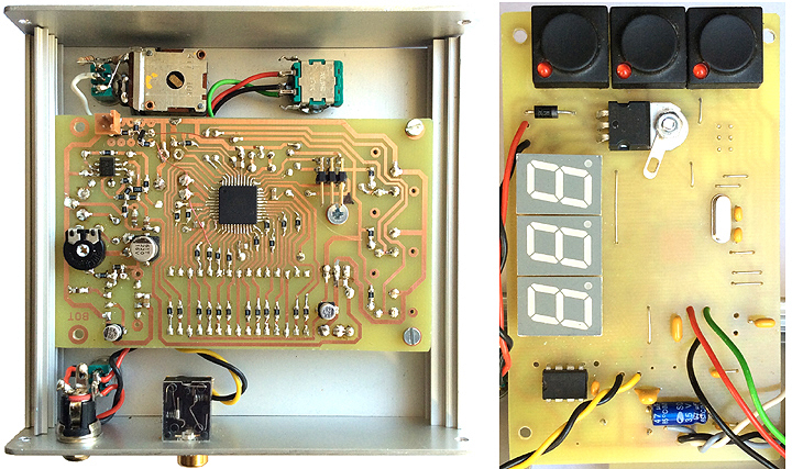
A proposal for a single layer PCB is presented. In general I prefer conventional wired components. But due to the large number of resistors, the PCB essentially was designed with surface mounted ICs, resistors and blocking capacitors. For frequency critical capacitors however, conventional parts are used (were just available here). The sine wave output level may be adjusted by a potentiometer, additionally reduced by a -20dB attenuator switch.
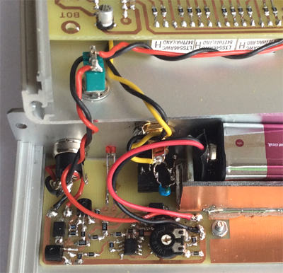
The circuit is designed for 9Vdc low ripple power supply (regulated AC/DC converter or 8.4V accumulator). Supply current is about 40mA. At the right bottom corner of the enclosure, space is reserved for a standard 8.4V NiMH accumulator.
Postscript March 2016
A charger for the accumulator has been added:
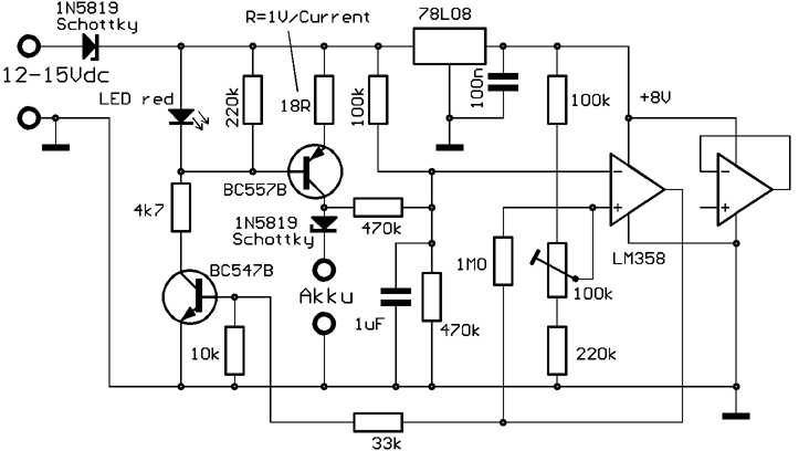
 The BC557 transistor works as a current source. The LED (2mA low current type) serves as reference voltage and displays active charging state too.
The LM358 opamp is wired as Schmitt Trigger and in combination with the BC547 transistor it controls the current through the LED, i.e. switches the current reference on and off. The charging end voltage of the accumulator is adjusted with the potentiometer to ca. 10.05V, so charging starts again when the accumulator voltage falls below 9.0V. A charge cycle starts automatically when the external power gets supplied. While the external power supply is off but stays connected, the accumulator is effectively not dischharged. With the 18 Ohm emitter resistor, the charge current is about 56 Milliamp, which is correct for a "fast charge" capable accumulator with 280mAh. As the supply current of sine wave generator is less, charging and operation works simultaneously. The same circuit is in use here to charge a pile of 7 "Micro" ("AAA") accumulators. Then an emitter resistor of 10 Ohm feeds a charge current of 100mA. The BC557 transistor is replaced then by a stronger type 2N2905A. |
Downloads:
The subsequently downloadable material is copyrighted (c)2015-16 by Wolfgang Schemmert.
Assembly and use of the device is permitted for free by everybody for any purpose ("freeware")
All information is based on best knowledge, but without any warranty. Any responsibility is excluded.
Single layer PCB layout (1:1 TIF format)
is in correspondence with the schematic, but not identical with the photograph shown above. Some bugs of the prototype board are corrected.
Firmware source code written in ATXmega assembler language (text file)
(recommended Fuses configuration for ATXmega32A4:
FUSEBYTE0:0xFF, FUSEBYTE1:0x77, FUSEBYTE2:0xFF, FUSEBYTE4:0xF0, FUSEBYTE5:0xEB)
Source code for sine wave calculation support program written in C (text file)
* Right of technical modifications reserved. Provided 'as is' - without any warranty. Any responsibility is excluded.
* This description is for information only. No product specifications are assured in juridical sense.
* Trademarks and product names cited in this text are property of their respective owners.