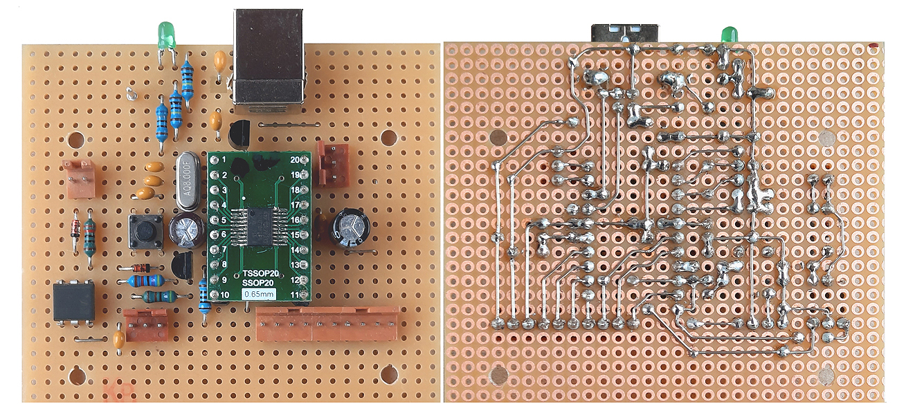
USB to MIDI or RS-232 Interface with STM32F042 on Veroboard
A DIY project is described for an USB to MIDI (or RS-232) interface based on the STM32F042F6 microcontroller (20 pin TSSOP) built on a Veroboard. Hard - and firmware are compatible with STM32F070F6 (20 pin TSSOP) processors too.
The microcontroller has to be soldered on a commercially available 20pin TSSOP to 20pin DIL breakout board.
This hardware design with STM32F042F6 or STM32F070F6 processor was originally developed for the CForth interpreter, but has almost the same I/O features as the small USB to MIDI (or RS-232) interface. For this dual use capability it is added here. It is less compact but needs less "technology" for reproduction.
The actual CForth version for these two boards can be configured by jumper into a
-- USB serial COM to USART-RS232 interface or
-- USB-MIDI to conventional USART-MIDI interface or
-- USB serial COM to conventional USART-MIDI interface
Details see CForth Operating Manual p.15.
From this point of view, the firmware described below seems to be a little bit outdated. The CForth version may be a more versatile alternative.
Furthermore, an alternative version for the STM32 Nucleo-L476 is described in parallel at this website.

Assembly of the STM32F042 interface on Veroboard.
The interface is "full speed USB2.0" grade. The 5V supply is scaled down by a linear low drop regulator to 3.3V, which supplies the complete board except the serial output driver (total current about 26-30 mA, depending on operating conditions).
The basic mode of operation is "transparent" bidirectional transfer of a byte stream. By default, the interface works as a virtual COM port seen by the PC. When a jumper or switch is placed between microcontroller port pin PA14 and Ground, it works as a native USB/MIDI interface.
A simple combined MIDI and RS-232 port hardware is provided on the board with separately wired connectors.
The combined MIDI/RS-232 OUT is made very simple: The level is inverted inside the microcontoller, so no external driver is needed.
For this reason, the TxD "logical 0" level is only 3.3Volt, a 100 Ohm resistor is added as short circuit protection. This has been tested with several third party RS-232 inputs, which typically have a trigger level around 0.7 Volt and an input impedance in the order of 5kOhm.
Somewhat more critical is the use of this Tx driver as MIDI OUT. With a modified connector wiring (see construction manual) commonly used MIDI interfaces and optocouplers are safely driven with 5mA or more.
A pinhead connector is provided on the PCB, which breaks out all user accessible I/O pins of the microcontroller for additional tasks plus Ground, +3.3V and +5V.
Supported by the provided firmware, up to 7 potentiometers or pushbuttons can be installed there to trigger user programmable input change messages merged over the transparent data transfer. This feature is switched ON and OFF with a jumper or switch between pin PA13 (programming connector) and Ground.
Individual USB Vid/Pid, baud rates and format of input change messages are user configurable. During RS-232 operation, a special configuration mode gets activated with fast keyboard sequence '+++'. For the serial connectors baud rates 9600, 19200, 38400, 57600, 115200 and 31250(=MIDI) are user configurable. The baud rate for each mode of operation (virtual COM port or MIDI) is configured individually. This way, the device may work as a data bridge between MIDI and RS-232 "worlds".
The user setup can be stored nonvolatile in the microcontroller flash.
The module can be programmed with ST-LINK, which is connected to the 3 pin conncector near pin20 of the microcontroller breakout board. Details see construction manual.
A detailled construction manual (HTML file) and an operation manual (PDF file) is available.
Downloads:
Firmware "usbmidicom-f042-vero.hex" for the STM32F042 / STM32F070 Veroboard version
Source code "usbmidicom-f042v10.zip" for the STM32F042 USB to MIDI or RS232 converter
The subsequently downloadable material is copyrighted (c)2016-24 by Wolfgang Schemmert.
Assembly of the devices, programming and use of the software is permitted for free by everybody for any purpose ("freeware"). For commercial use, restrictions of third-party software contributors (Segger GmbH, STM) must be respected.
All information is based on best knowledge, but "as is" and without any warranty. Any responsibility is excluded. Use for dangerous, life-threatening and medical applications is forbidden.
Bugfix Nov2024: to save updated user setup into Flash, now command code is '~'.
(21 November 2024)
(21 November 2024) This source code is provided as complete "Segger Embedded Studio" project (ZIP file, 335 kB).
Parts published by Segger GmbH are under license of Segger&|Rowley, parts published by STM are under license of STM, parts programmed by me are provided under GNU GPL3 license.
![]()
* State of information November 2024.
* Right of technical modifications reserved. Provided 'as is' - without any warranty. Any responsibility is excluded.
* This description is for information only. No product specifications are assured in juridical sense.
* Trademarks and product names cited in this text are property of their respective owners.
 back to menue